Serial PWM Driver with optional OLED display
Firmware version: 1.5
Hardware version: 1.45
Table of content:
- Requirements
- Optional feautres
- Required input line over serial communication
- Testing, prototyping
- PCB design
- Measurements
- ToDo list
- Changelog
Requirements
-
This device can control individual PWM outputs as “channels”.
-
It get commands from any other device over serial communication.
(e.g.: from a Raspberry Pi or a Bluetooth Serial module)
-
It need to be able to control any DC device at least with 5A power consumption per channel.
-
Need to elecrically separete output channels from MCU circuit and from connected serial device to protect own board and the attached device on the other side of serial communication in case of any electrial issue. (This will separation is that what will be named as “MCU-side” and “output-side” of this board.) This separation based on optocouplers.
-
More output channels need to be able to updated in same time even if any of those channels has no new value (e.g. When it drives RGB lights and new commands contains only the red and green values)
Used MCU:
Arduino Nano v3 (eBay link)
Number of output channels:
6 channels with 8 bit PWM outputs - based on physical limitation of arduino board.
Note: Can handle 12bit inputs too.
For this function define macro:

    USE_12BIT_INPUT_VALUES
Optional feautres:
Display can be used (required library: Arduino-SSD1306 Ascii ):
Can handle simple oled display over I2C or SoftSPI protocols to show current values.
For this feature define one of the following macros:

    USE_OLED_DISPLAY_I2C or
    USE_OLED_DISPLAY_SPI

Important note:
    Do not define any "USE_OLED_DISPLAY..." macro (comment it out) if display is not connected.
    It will stop working when it tries to communicate with the display and there is no display.
Handling further channels
Can handle more than 6 channels (what is the physical limitation
by number of pwm channels on Arduino Nano board)
If this feature is in use, then it forwards the received commands for a "slave instance"
when the channel id (of the received command) is over the range of "own channels".
A second, SoftwareSerial bus is used for forwarding of command to the slave instance of Serial PWM driver
For this feature define the following macro:

    HANDLE_FURTHER_CHANNELS
Required input line over serial communication
Input line for any channel: channel_num value

| Input mode | Using "further channels" option | channel_num | value   |
| ---------- | ------------------------------- | ----------- | ------- |
|    8 bit   |              No                 | 0..5        | 0.. 255 |
|    8 bit   |              Yes                | 0..ch_max   | 0.. 255 |
|   12 bit   |              No                 | 0..5        | 0..4095 |
|   12 bit   |              Yes                | 0..ch_max   | 0..4095 |

ch_max: depens on the count of devices (= 6 * device count)

Examples: 0 255
          5 4095
Testing, prototyping
Serial connection with a Raspberry Pi Zero
Serial PWM Driver board get commands over strandard serial communication.
In my case the other device (what sends the commands) will be a
RaspberryPi Zero (link below).

RaspberryPi (and many other devices) using serial communication
with signal level of 3,3V.
In direction of Pi -> Arduino it works fine, because arduino can read Pi's
3,3V "high" signal as a "high" signal, since it is significantly higher
voltage than 2,5V (what is the middle of range 0V-5V), but:
In direction of Arduino -> Pi we have to apply a voltage divider to make
arduino's 5V signal level lower to protect the RaspberryPi.
For this we can use simple resistors with values of 220 and 470 Ohm,
to create a 3,3V signal from Arduino's TX signal.

Note: According to the measured power consumtion of
Serial PWM Driver board on MCU side, it can be powered directly
from VCC of RaspberryPi.
If it needed because of any reason, Serial PWM Driver board can powered
  - from external VCC (over it's VCC connector)
  - from external raw input (6V-15V over RAW connector)
Important:
  If Serial PWM Driver board is powered from any external source
  (what is not the same as the power source of connected serial device),
  then the VCC (5V) connection of "Serial In" MUST be interrupted
  (via the jumper on the board).
MCU side power consumtion can be found below
Sample connection between Serial PWM Driver and RaspberryPi:

Breadboard testing
Testing v1.1 and v1.2 with display:
v1.1 with I2C display
 v1.2 with I2C display and sample output RGB leds

Testing v1.3 with 2 instances with I2C and SPI displays:
Two instances (left one is the “master device” with blue I2C display and “FURTHER_CHANNELS” feature enabled, right one with white SPI display)
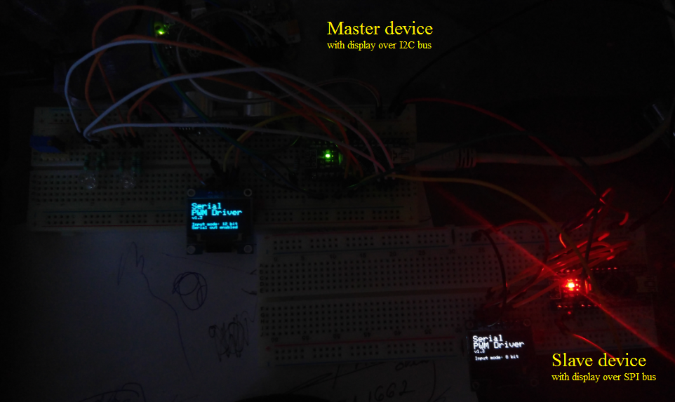
Send pwm commands from raspberryPi using the attached python script:

Two instances after command has been received

Breadboard testing with all parts on output side
Firmware:          v1.3
Used layout as Hw: v1.44


PCB design
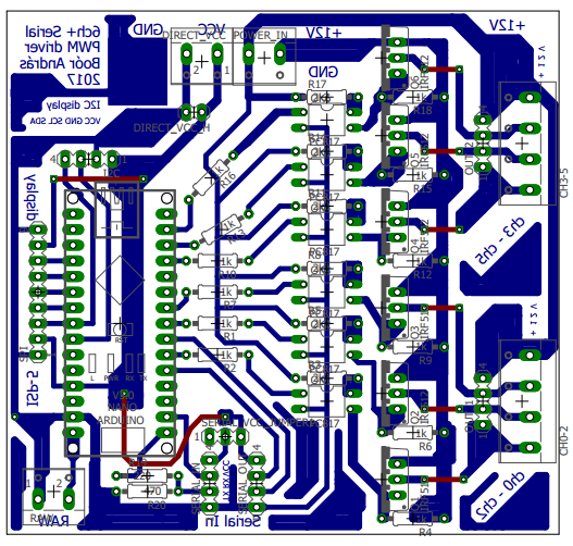
Eagle schamatic available as zip & pdf:
Serial_PWM_Driver_eagle_design
PCB design as PDF
Part list available as HeStore basket:
PCB prototype (hw v1.45)


First prototype dry test
- Firmware v1.3
- Hw v1.45

Final placing

Measurements
Power consumption
On MCU side:
| Condition | Consumption on VCC |
|---|---|
| 0% output on all channels | 25,6 mA |
| 100% output on 1 channel | 29,0 mA |
| 100% output on 3 channels | 36,2 mA |
| 100% output on all channels | 46,8 mA (calculated) |
Memory and program storage utilization on ATmega328 (Arduino Nano v1.3):
| Option(s) used | Program storage | Dynamic memory | Sw version |
|---|---|---|---|
| With I2C display and using further channels | 9018 bytes (29%) | 429 bytes (20%) | v1.4 |
| Without any optional feature | 8876 bytes (28%) | 425 bytes (20%) | v1.2 |
ToDo
- [x] Modify pinout config of softSpi display according to the pin order on display’s pcb.
- [x] Modify PCB design: Leave enaugh space between arduino and optional I2C display (when display connected directly on the board).
- [X] Modify PCB design: Add pin-header to SoftSPI connection of optional display (it should be 2-sided (rotateable) if it’s possible)
- [X] Add termial connector for using optional 5V power supply for arduino (e.g. get VCC power directly from raspberry)
- [X] Measure the power consumption before start using with direct 5V power supply (31mA)
- [X] Check appropirate layout (enaugh space for connect additional boards directly)
- [X] Create RTU PCB version
- [X] Build first usable prototype
- [X] Testing with real output devices
- [X] Measure power consumption with real output devices
- [X] Implement requirement to update RGB channels together
- [ ] Update PCB design with missing labels (hw version, serial output)
Changelog
v1.5
  Store output values for recover after restart device.
  After restoring values, it will save 0 value for all channels.
  Thereby all output channel can be set for 0 with restart twice.
v1.4
  Output channels can be linked together, to be able to update
  RGB channels together in same time
v1.3
  Add optional feautre for handling more channels with fowarding to an other instance
v1.2
  Add optional feautre for handling 8 and 12 bit wide input values
  (output works with 8 bit resolution in all case.)
v1.1
  Add optional feautre for using I2C or SPI display
Created by:
Andras Boor
2017.01